Listen to this blog ...
When it comes to printed circuit boards (PCBs), every tiny detail matters. Whether you’re a product engineer or a manufacturer assembling electronics at scale, even the smallest mounting misstep can snowball into performance issues, overheating, or outright failures.
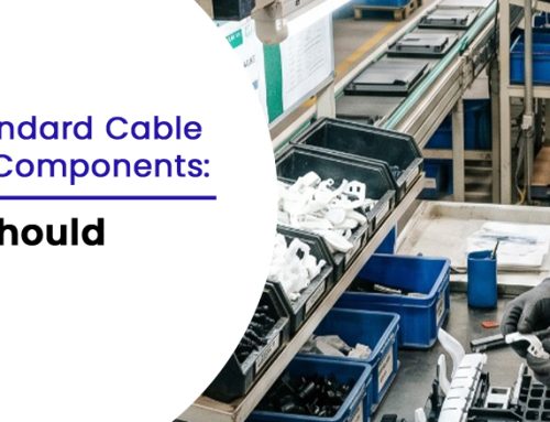
One of the simplest components often overlooked? PCB spacers.
These small parts, typically made from plastic or nylon, do much more than simply hold the board in place. They provide electrical insulation (when non-conductive), add structural support and even aid in thermal management by keeping enough clearance for airflow. Choose the wrong one, or mount them incorrectly and you
risk compromising the reliability of the entire system.
Let’s explore five common PCB mounting mistakes and how choosing the right spacer can quietly solve them before they become costly problems.
Table of Contents
- Mounting the PCB Directly to the Base
- Using the Wrong Spacer Height
- Overlooking Electrical Insulation
- Using Spacers That Don’t Fit Securely
- Ignoring Thermal Spacing
- Conclusion
1. Mounting the PCB Directly to the Base
Mounting a PCB flush against the base or enclosure, especially a metal or conductive one, may seem like a time-saver, but it leaves no room for airflow and increases the risk of electrical shorts from contact with conductive surfaces.
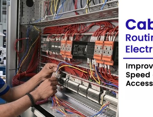
Using non-conductive plastic spacers solves both problems. These components elevate the board, allowing for airflow and safe separation. To complement this, in setups where external wiring is connected to the PCB, integrating accessories like plastic wire clips or electrical wire holder clamp can help organise wires and reduce the chance of accidental contact with components or traces.
Need quality mounting parts? Connect with a trusted cable tie mounts supplier.
2. Using the Wrong Spacer Height
Incorrect spacer height is a subtle but serious issue. When a spacer is too tall or too short, it may cause the PCB to warp or bend, putting unnecessary stress on solder joints, connectors and the board itself.
This issue often goes unnoticed until performance problems or physical damage appear later in the product lifecycle. Ensure you’re using precision-sized circuit board spacers and make sure nearby cable routing with tie mounts or zip ties doesn’t create extra pull or strain on the board, helping maintain both electrical integrity and physical stability.
3. Overlooking Electrical Insulation
Using the wrong type of spacer can lead to short circuits or EMI-related issues, especially in compact PCBs with high-voltage or sensitive signal lines. This is a common mistake when space is tight and grounding paths aren’t carefully managed.
To prevent this, use plastic or nylon spacers. These non-conductive options help maintain safe clearance and reduce the risk of electrical faults. For added safety and clean cable routing, include accessories like wire holding clips or electrical wire holder clamps. These keep wires organised, prevent them from shifting during operation and stop them from coming into contact with live components or exposed traces.
4. Using Spacers That Don’t Fit Securely
If a spacer doesn’t lock in properly or if the mounting hole tolerances are off, the PCB can become unstable. Movement during transport, vibration in machinery, or thermal cycling can all lead to connector fatigue, cracked solder joints, or even trace damage.
To ensure solid structural stability, use snap-fit or threaded spacers that match the board’s exact mounting specs. For added protection, couple them with plastic wire clips and wire tie mounts to secure surrounding cables and prevent accidental tugs that could dislodge the board or strain connectors. For reliable components that won’t fail under pressure, it’s always best to work with a reliable cable tie mounts supplier.
5. Ignoring Thermal Spacing
Thermal performance is just as important as structural integrity. Mounting boards too close to each other or to the enclosure restricts airflow, increasing the risk of overheating.
Use plastic or nylon spacers to maintain proper spacing between PCBs and surfaces,allowing air to circulate freely. When combined with smart cable management using cable zip tie mounts, wire holding clips and plastic wire clips, you can improve airflow and reduce thermal stress, often reducing reliance on additional cooling solutions.
Proper spacing with the right components contributes to safer and more efficient electronic assemblies.
Looking for reliable plastic mounting parts? Explore our full range of spacers, clips and cable tie
mounts built for durable PCB assemblies.
Why Choosing the Right Spacer Manufacturer Matters
As a leading PCB spacer manufacturer, we understand that every board has unique
requirements. From custom dimensions to different materials (nylon, plastic, or metal), we manufacture spacers that
meet the highest quality standards. Choosing a trusted supplier ensures:
- Consistent quality across batches.
- RoHS and ISO-certified manufacturing.
- Fast delivery with ready stock options.
- Custom solutions for OEMs and electronics manufacturers.
Conclusion
Spacers may be small but their role in PCB performance is significant. From reducing board flex and aiding airflow to ensuring proper insulation and stability, choosing the right spacer helps avoid common mounting mistakes that often go unnoticed until failure happens.
Paired with organised wiring using plastic wire clips, wire tie mounts and electrical wire holder clamps, the right mounting approach results in cleaner, safer
and more reliable assemblies.